How I Built My Level 3 Project
Ready for your Level 3? If so, here is my documentation I put together that I refer too time and time again. It is by no means the definitive guide on how to build High Powered Rockets. It is my way. Only through lots of mistakes and trial and error was I able to create Projects that now command attention at almost any launch.
You are welcome to use this material for your own education and learning. If you find a better way or have your own method of creating your High Powered Rocket - please e-mail me and I can include it into this website. This is a LEARNING WEBSITE and I welcome your comments.
You are welcome to use this material for your own education and learning. If you find a better way or have your own method of creating your High Powered Rocket - please e-mail me and I can include it into this website. This is a LEARNING WEBSITE and I welcome your comments.

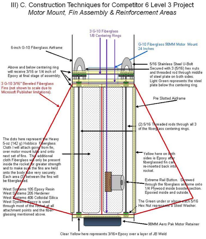
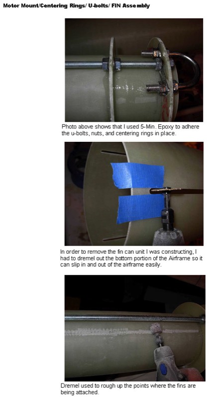
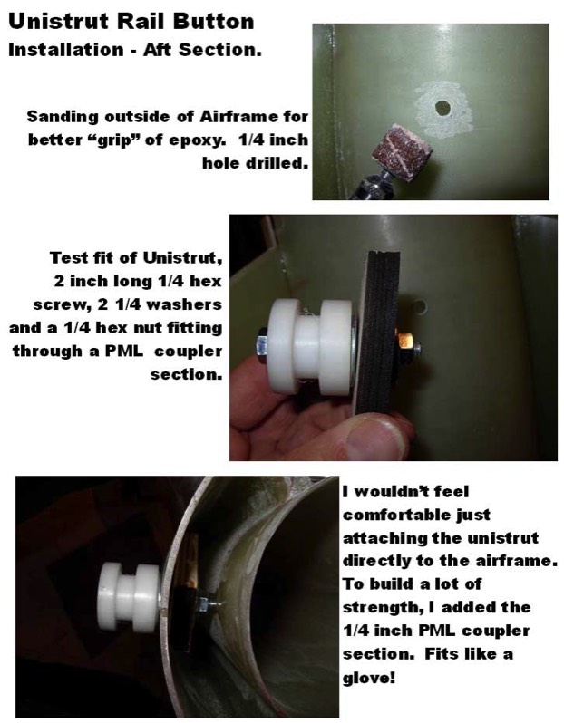
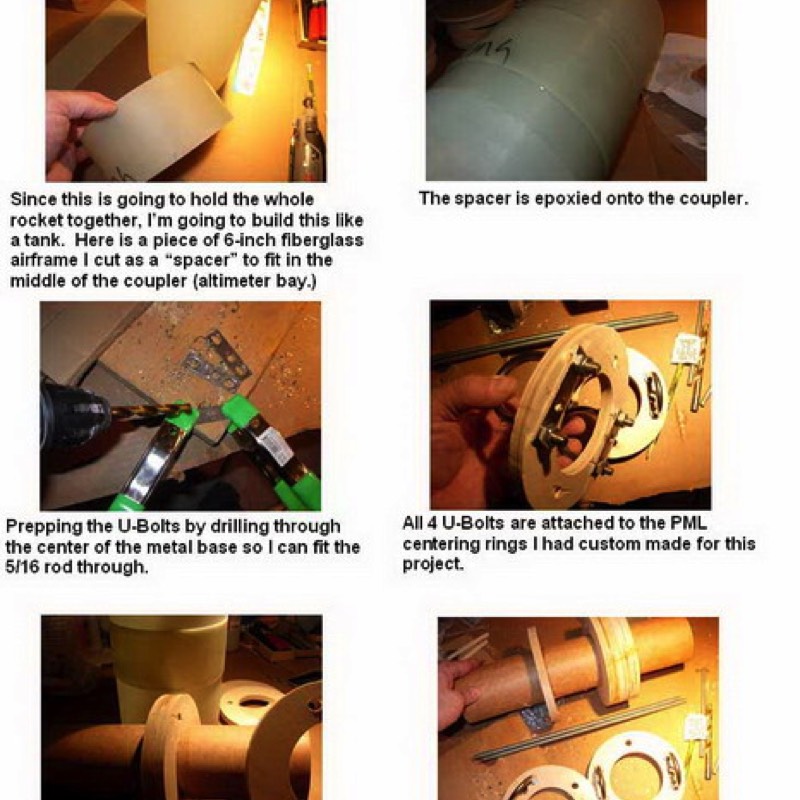
OK - so how do you build a rocket thats as strong as a rock? Follow the steps here and you will prevent damage from hard landings and have less repair work after your flight. Here we are going to attach U-Bolts and a threaded rod to our centering ring.
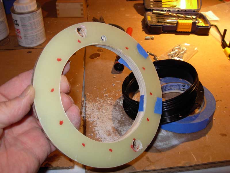
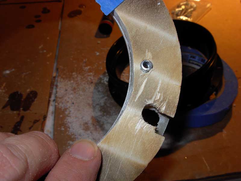
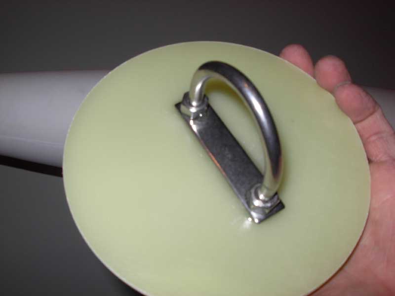
Drilling the center of the top centering ring right through the the metal strip to hold the upper most part of the threaded rod.
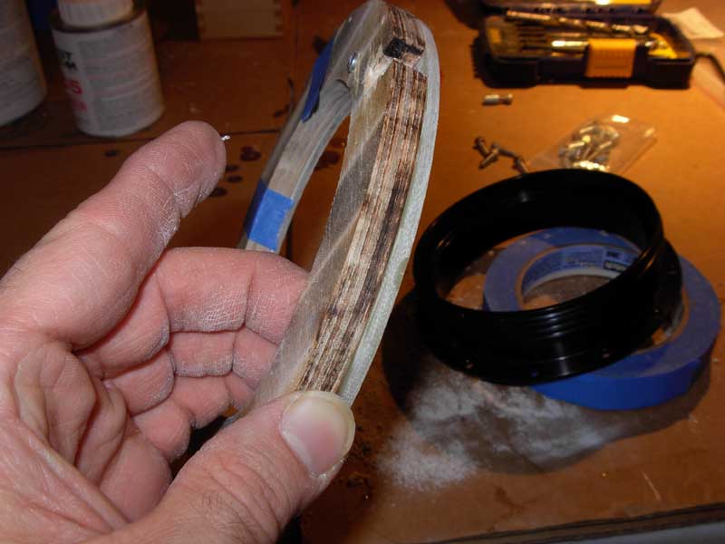
Below both sides are completed.
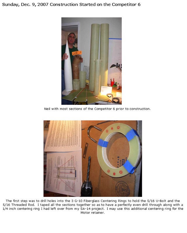
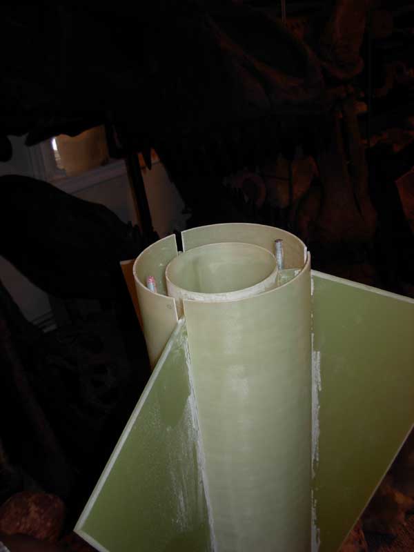
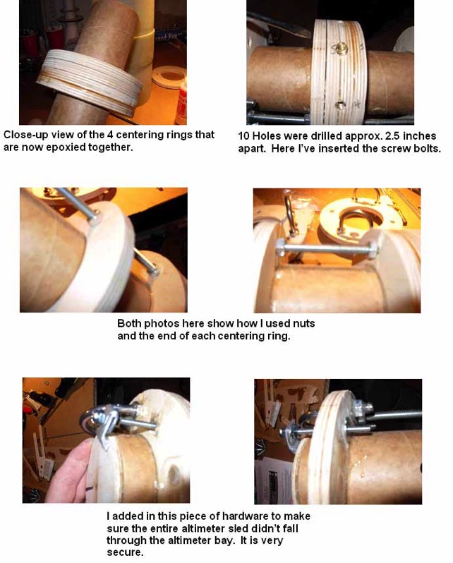
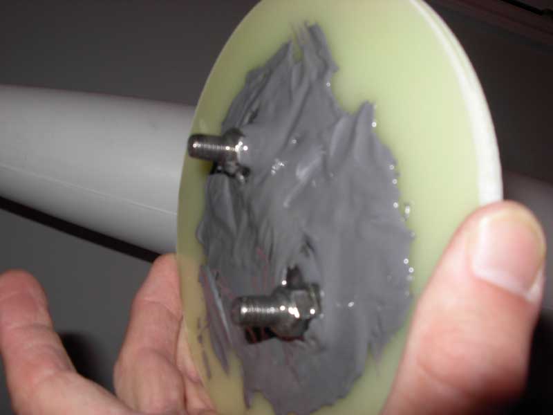
I cut the threaded rods 2-ft in length to fit between all the centering rings. I then sanded the inner and outer part of the centering rings and placed the unit together for a “test-fit” you see above. The above photo is a detailed view of how I attached the U-Bolt to the top of the centering ring. Note that the threaded rod will hold all the centering rings together to essentially make this one single very strong unit especially after I fiberglass and fill this area with Giant Leap Expanding Foam.
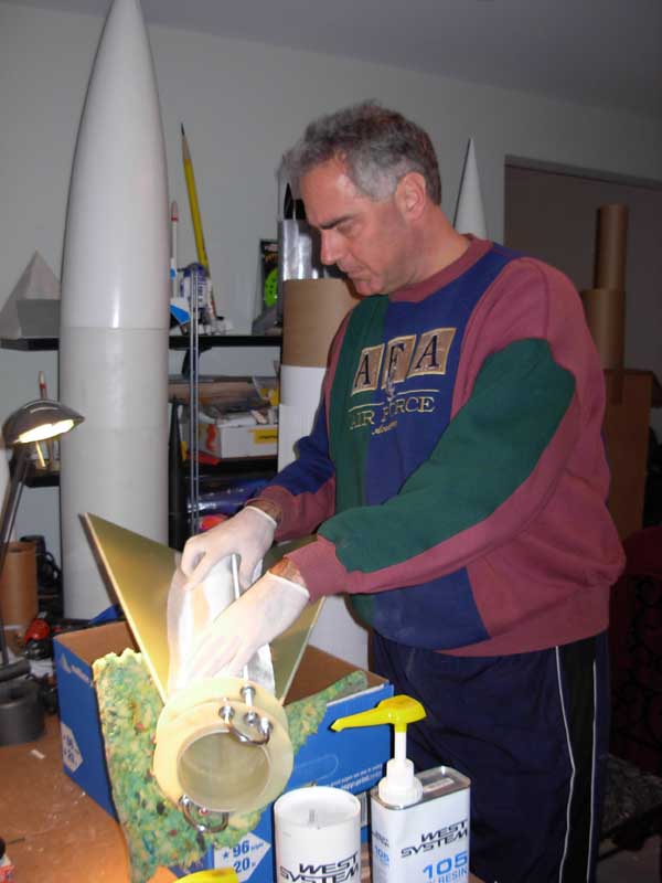
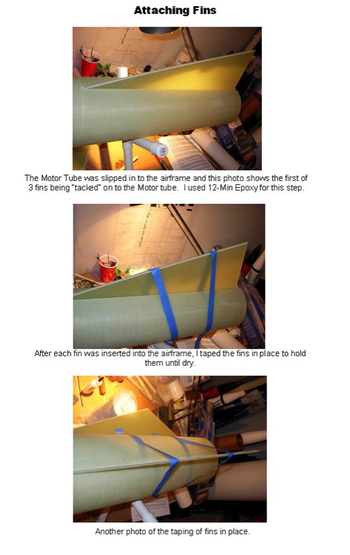
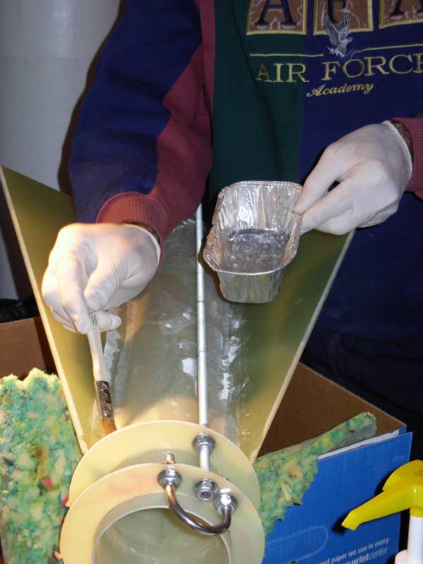
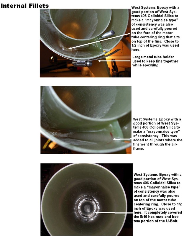
ABOVE: Measuring 5-oz fiberglass to be overlaid 1-0inch on the fin, over motor mount, and then 1-inch over next fin. West Systems epoxy is used exclusively for this process.
BELOW: Applying West Systems Epoxy on motor mount prior to placing fiberglass on top.
BELOW: Applying West Systems Epoxy on motor mount prior to placing fiberglass on top.
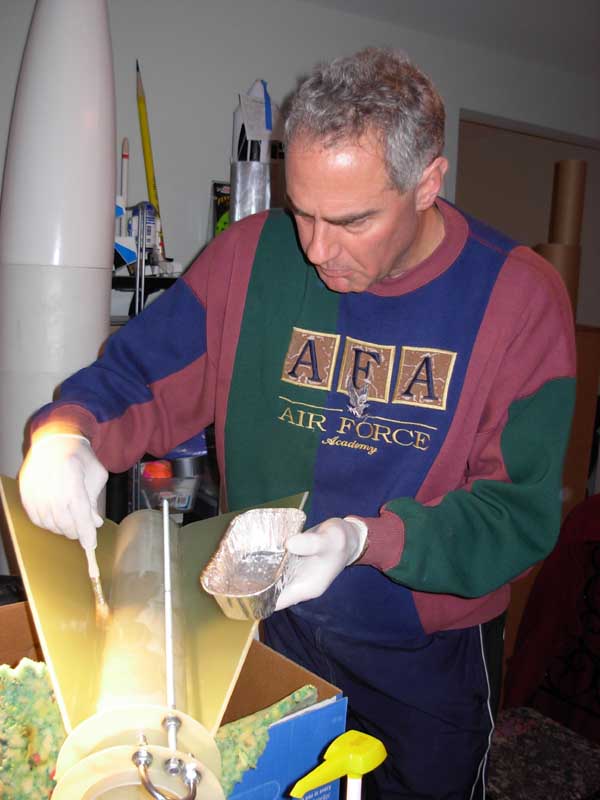
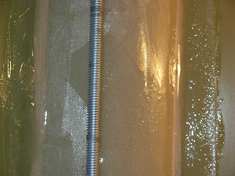
ABOVE: Fiberglass laid on this section. Adding a bit more West Systems Epoxy as needed.
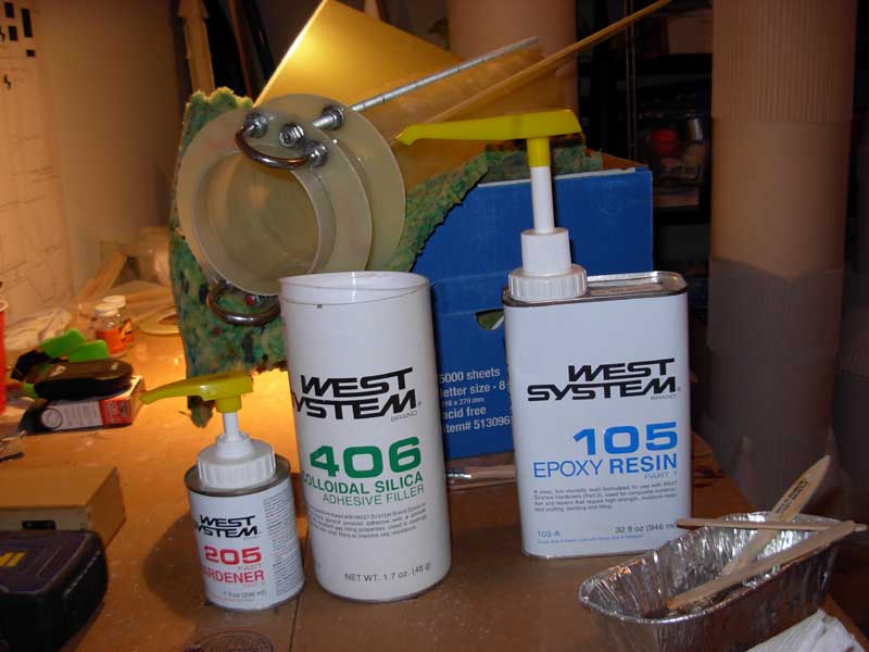
BELOW: West Systems Epoxy
BELOW: West Systems Epoxy
BELOW: See fiberglass epoxied to motor tube and 1-inch on fin.
ABOVE: Fin can is now re-inserted back into the airframe.
BELOW: Aft view of the airframe with fin can inserted.
BELOW: Aft view of the airframe with fin can inserted.

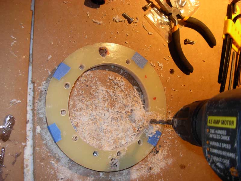
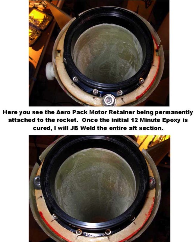
ABOVE: I am using the 98MM Aero Pack Quick Change Motor Retainer. This photo shows how I marked off all the holes that need to be drilled for the screws.
BELOW: Attached to the G-10 Fiberglass Centering Ring is a extra centering. The goal here is to drill through both the fiberglass and the wood and attach both together for much greater strength and holding power. The G-10 fiberglass centering ring will be epoxied to the wooden centering ring. The screws go through the motor retainer then through the G-10 centering ring and then into the wooden centering ring.
BELOW: Attached to the G-10 Fiberglass Centering Ring is a extra centering. The goal here is to drill through both the fiberglass and the wood and attach both together for much greater strength and holding power. The G-10 fiberglass centering ring will be epoxied to the wooden centering ring. The screws go through the motor retainer then through the G-10 centering ring and then into the wooden centering ring.
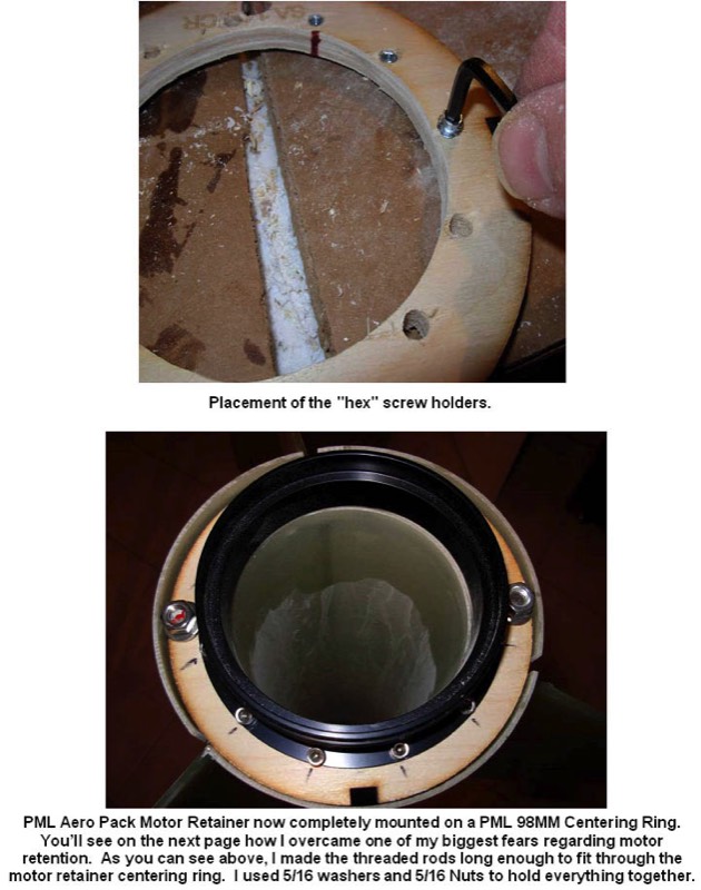
ABOVE: This photo shows the placement of one of the “hex” crew holders.
BELOW: Drilling the balance of the required holes.
BELOW: Drilling the balance of the required holes.
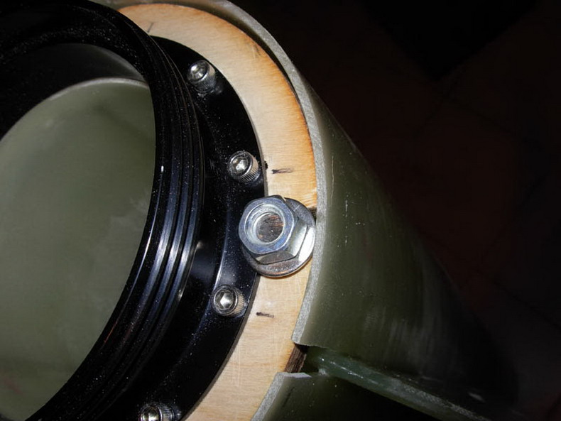
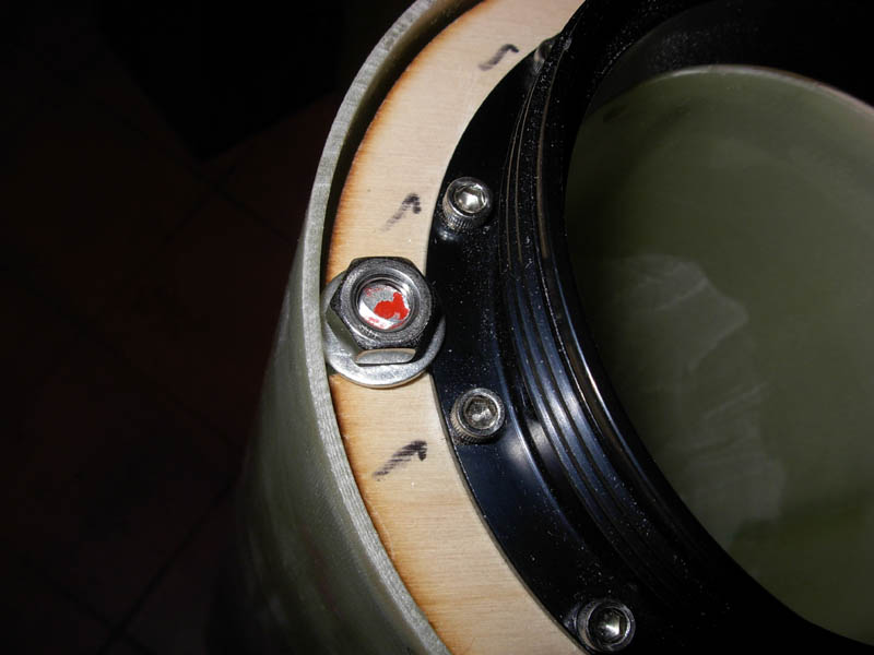
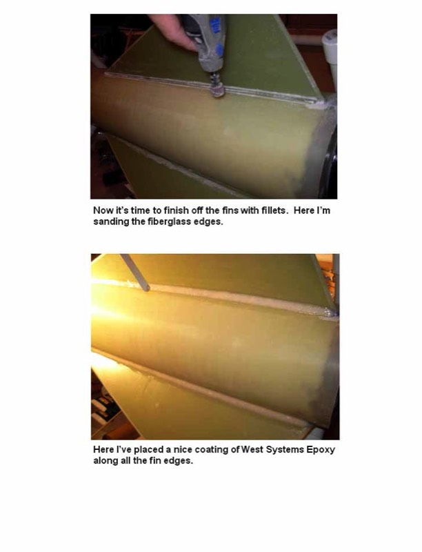
Close-up of how the threaded rod went through the motor retainer centering ring where I attached a 5/16 washer that overlapped the motor retainer and fit a 5/16 nut over that. this is only for test fitting right now. After I attach the Unistrut rail buttons and foam the interior, I’ll close up the aft section, JB Weld and epoxy the entire unit shut.
Nose Cone
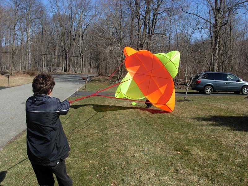
My son Jeremy testing the parachute.
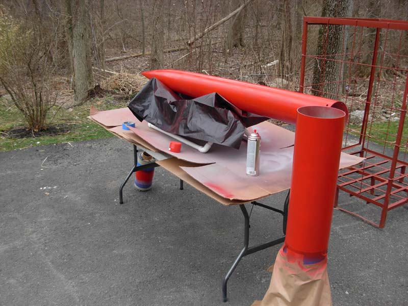
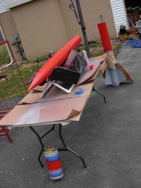
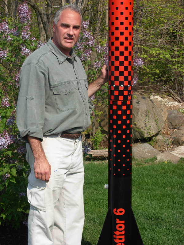
Above and below - painting the Competitor 6
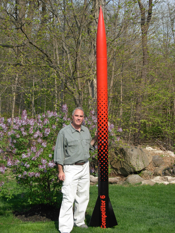
Finished after application of these really cool decals.
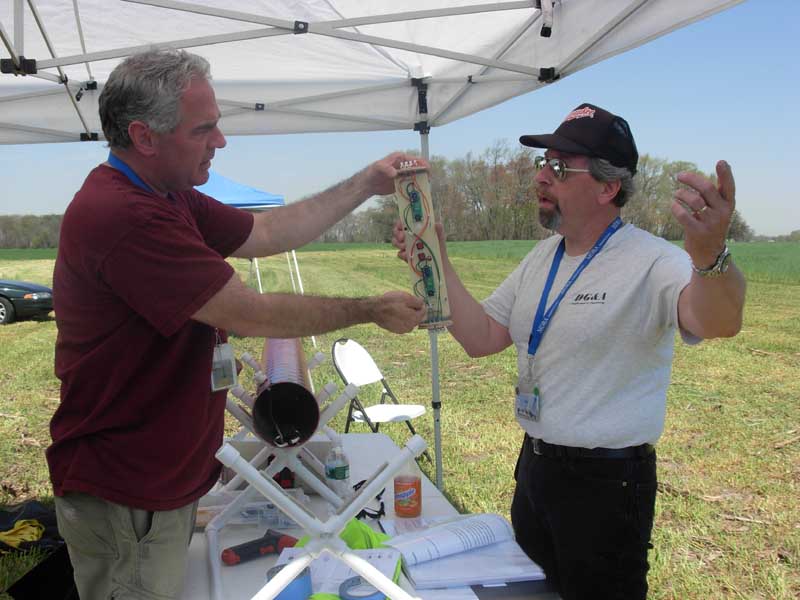
Dan Michael reviewing my flight plans.
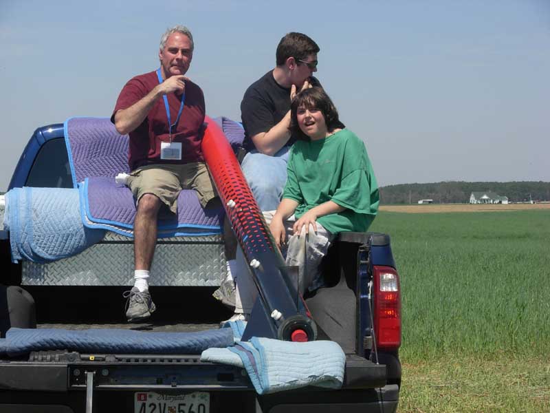
On the truck on the way to the Away Cell
Arming the Altimeters
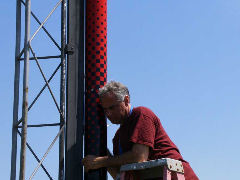
Listening for the correct amount of “beeps” from my altimeter.
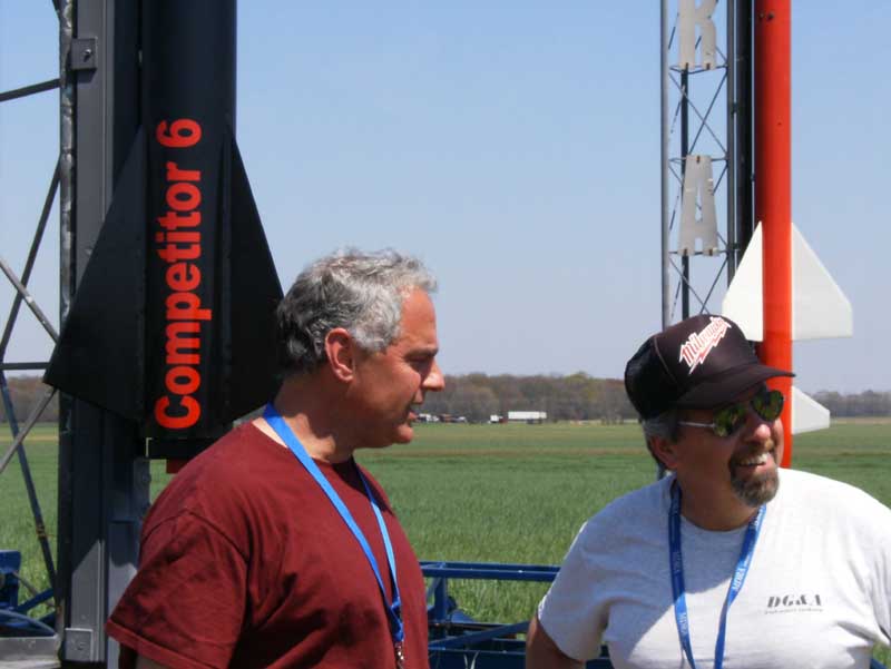
My nervous heart is beating 2000x a minute and Dan is laughing at me.
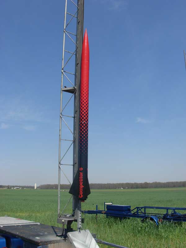
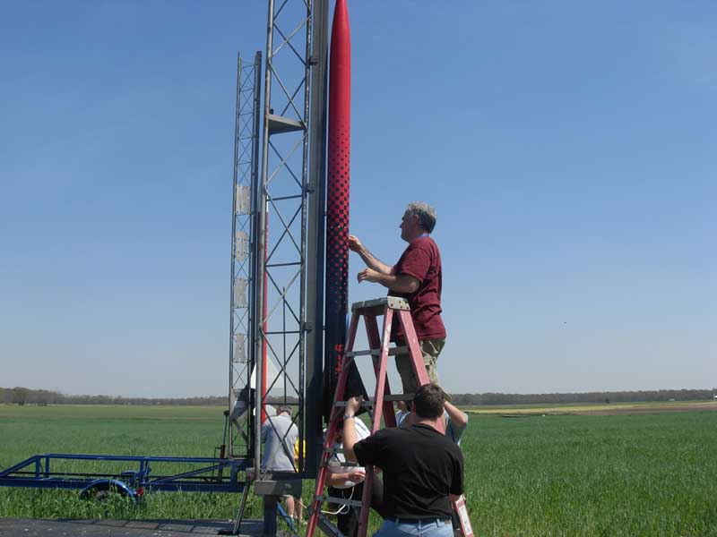
Ready for launch.
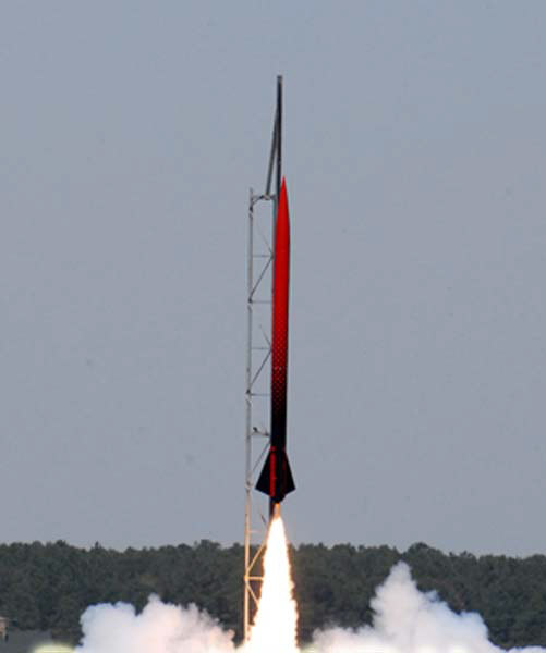
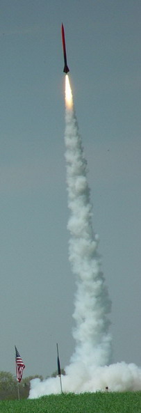
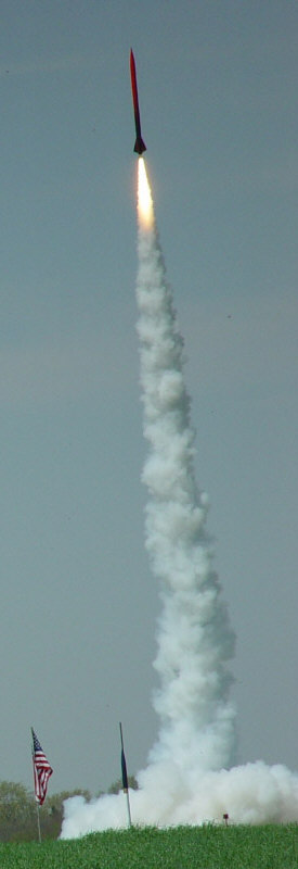
Liftoff - see videos of the actual Level 3 flight at top of this page.
Top